
Aluminum extrusion is the default construction set for machine frames: modular, straight, and easy to assemble. But a CNC gantry or a 3D printer frame built from extrusion is a structure, and structures deflect under load. The spindle pushes against the workpiece, the workpiece pushes back, and the extrusion between them bends by an amount the cutting tool then faithfully reproduces as dimensional error. Knowing the deflection limits of your extrusion profiles under spindle load is what separates a frame that cuts accurately from one that merely looks rigid. The math is standard beam theory, and it is worth doing before buying a single length.
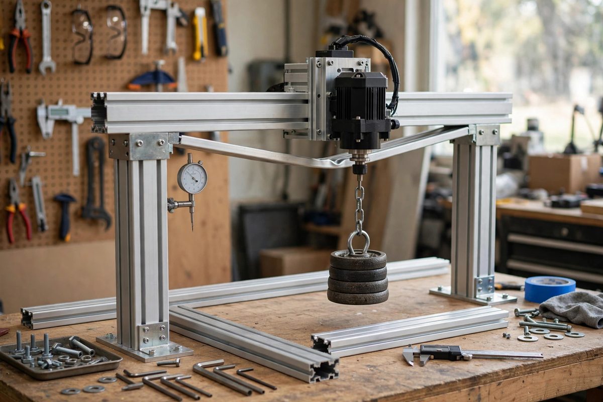
Where the deflection comes from
Cutting forces at the spindle resolve into loads on the gantry: the tool pushes the work, the work pushes the tool, and the gantry beam spanning between its supports bends under the difference. For a beam supported at both ends with the load in the middle, deflection grows with the cube of the span and inversely with the beam's stiffness, which is the product of the material's modulus and the profile's area moment of inertia. The cubic dependence on span is the dominant fact: doubling the gantry span increases deflection eightfold for the same profile. This is why wide-format machines need disproportionately beefier gantries, and why the most effective stiffness upgrade is often shortening the span rather than upsizing the profile.
Reading profile specifications
Extrusion manufacturers publish the area moments of inertia for their profiles, usually for both principal axes, since the T-slot cross-section is not symmetric. Use the value for the axis that resists your actual load direction; the strong axis and weak axis of a rectangular profile differ substantially, and orienting the profile with its strong axis against the cutting force is free stiffness. The published values assume the plain profile; brackets, joining plates, and the compliance of the connections all add deflection the beam calculation does not capture. Treat the beam math as the best case and the joints as the tax. In practice, connection compliance often dominates the total deflection of an extrusion frame, which has major implications for how you spend your stiffness budget.
Setting a deflection limit
A deflection limit is a tolerance decision, not a physics constant. The frame's deflection under cutting load should be a small fraction of your target part tolerance; a common rule budgets roughly a tenth of the total tolerance to the frame, leaving the rest for the tool, the workholding, and thermal effects. Translate that into an absolute number: if you want to hold a tenth of a millimeter on parts, the frame should deflect only about a hundredth under typical cutting forces. Estimate your cutting forces honestly for the materials and depths of cut you actually run; aluminum at aggressive depths generates far more force than wood or plastic at finishing passes. Size the frame for the real loads, not the brochure loads.
What the calculation typically shows
Run the beam numbers for a mid-size gantry and a pattern emerges: the bare extrusion is usually adequate for light finishing work but marginal for heavy roughing, and the joints are the weak link in both cases. A single central gantry beam on a wide machine often fails the deflection budget for aggressive cuts, which is why serious machines use paired beams, box sections, or steel reinforcement. The Z axis deserves its own calculation, since the spindle's overhang from the gantry creates a moment arm that amplifies deflection; a long Z travel with the spindle at full extension is the worst case and should be the design case. Do the arithmetic for the extremes of the machine's envelope, not just the comfortable middle.
Stiffening strategies that work
When the numbers fall short, the fixes rank by effectiveness. Shortening spans beats everything: move supports inward, add a mid-span support, or narrow the machine. Next, improve the joints: gusseted corner brackets, through-bolting, and epoxy-leveling the mating faces all cut connection compliance dramatically. Then consider profile upgrades: larger profiles, paired profiles tied together into a composite beam, or steel inserts in the extrusion's core for the longest spans. Damping matters too: a frame that rings will chatter, so constrained-layer damping or simply filling voids with damping material can improve cut quality beyond what the static deflection numbers suggest. Spend the stiffness budget where the calculation says the deflection lives, which is usually the joints first.
Verifying the built frame
After assembly, measure the real deflection. Mount a dial indicator on the table, apply a known force at the spindle nose with a spring scale or a calibrated push, and read the deflection in the cutting directions. Compare with the calculation; if the measured deflection greatly exceeds the beam math, the joints are the culprit, and the fix is better connections, not bigger extrusion. Cut test parts and measure them: circles reveal backlash and compliance, straight slots reveal deflection under load. The measurement closes the design loop and tells you whether the machine meets its deflection budget or needs another round of stiffening. Trust the indicator over your intuition about rigidity; extrusion frames routinely feel stiffer than they are.
Extrusion deflection under spindle load is calculable, so calculate it: beam theory for the profiles, honest cutting forces, a deflection budget tied to your tolerances, and special attention to the joints where the real compliance hides. Verify with an indicator after building. A frame designed to its deflection limit cuts to its tolerance; a frame built on hope cuts to its deflection.
Related Guides
- T-Track Extrusion Rigidity Limits Under Lateral Loads: T-track is the backbone of modular jigs and fixtures: a slot in the bench or fence that accepts sliding bolts and hold-downs anywhere along its
- Mitering Dual Extrusion Rail Corners for Bench Jigs: Aluminum extrusion rails, the T-slot building blocks of bench jigs and fixtures, join at corners to make frames. The mitered corner, two rails cut at
- Standardized T-Track Spacing for Modular Jigs: T-track turns jigs from single-purpose contraptions into a modular system: stops, hold-downs, and fences slide, lock, and reposition along
- Standardized Miter Slot Detents for Swappable Sleds: Every table saw owner eventually builds a small fleet of sleds: a crosscut sled, a miter sled, a tapering jig, a box-joint sled. Each one rides in