
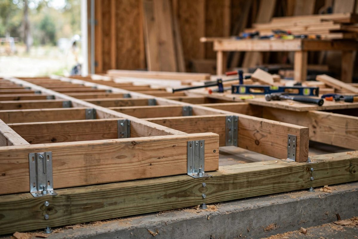
The rim joist is the quiet workhorse of floor framing. It caps the ends of the floor joists, ties them together, and transfers the edge loads of the floor down into the sill plate and foundation. Because it sits at the perimeter, it also carries concentrated loads that interior joists never see: the ends of bearing walls above, stair openings, and the occasional point load from a post. Sizing it by habit, the same board as the joists, works most of the time, which is why most builders never calculate it. But when the loads are unusual or an inspector asks questions, knowing how to check the rim joist's shear capacity turns a guess into an answer.
What the rim joist actually carries
Shear in the rim joist comes from vertical loads applied along its length that must travel down into the sill. The uniform edge load of the floor itself is usually modest. The demanding cases are point loads: a bearing wall or a post landing near the rim, which dumps a concentrated force into a short length of the member. The rim joist resists this by acting as a deep beam spanning between supports, developing shear force that peaks near the load and near the supports. Understanding this load path matters because the fix for an overloaded rim joist is not always a bigger board. Sometimes it is a shorter span, achieved by adding blocking or a support below, which cuts the shear far more effectively than upsizing the lumber.
The shear calculation in plain terms
Shear capacity of a wood member depends on its cross-sectional area and the allowable shear stress of the species and grade. The check itself is simple in concept: compute the maximum shear force from your loads, compute the shear stress as that force divided by the cross-sectional area (with the standard adjustment wood design applies for the parabolic shear distribution in rectangular sections), and compare it against the allowable stress. For a uniformly loaded rim joist, the maximum shear sits at the supports and equals roughly half the total load on the span. For a point load, the shear diagram jumps at the load, and the maximum is the larger reaction. The arithmetic is not the hard part. The hard part is honestly accounting for all the loads, including the ones the framing above quietly delivers to the rim.
Getting the loads right
Load takeoffs for rim joists go wrong in predictable ways. The common miss is the wall above: a bearing wall running parallel to the rim delivers its full weight, floor after floor, onto that edge member, and builders who think of the rim as just a joist cap forget to include it. Another is the concentrated load from a stairwell header or a beam pocket that lands on the rim between supports. Tributary width thinking helps: ask how much floor, wall, and roof area drains its load to each foot of rim. Be generous with the estimate rather than precise, because lumber varies and loads accumulate in ways drawings do not show. When the numbers are close, that is information: a member at ninety percent of capacity deserves a second look at the assumptions, not a shrug.
What the code and span tables assume
Prescriptive framing tables in the residential code cover conventional rim joists under conventional loads, which is why most houses never need this calculation. The tables assume standard joist spacing, ordinary residential loading, and common lumber species. Step outside those assumptions, with a long span between supports, an engineered lumber rim, a point load from above, or a nonstandard species, and the prescriptive path no longer applies. That is when the calculation earns its keep. Note also that shear is only one check among several: bending stress, bearing stress where the rim sits on the sill, and deflection all have their own limits, and a member that passes shear can still fail another check. Run the full set, or have an engineer run it, whenever the framing leaves the conventional box.
Practical reinforcements that work
When the calculation says the rim joist is overstressed, the most effective fixes shorten the span or share the load rather than simply upsizing. Solid blocking between the rim and the first interior joist, tightly fitted and nailed, transfers edge loads inward and dramatically cuts the shear in the rim itself. A second rim joist sistered alongside doubles the shear area at modest cost. Adding a support below, such as a post to the foundation, cuts the span and with it the shear forces. What does not work as well as people hope is swapping species for a slightly stronger grade while keeping the same dimensions; the gain is real but small compared with the geometric fixes. And whatever you add, connect it properly: reinforcement that is not well nailed or bolted to transfer the load is just lumber sitting nearby.
Know when to call an engineer
This calculation is a screening tool, not a substitute for engineering judgment. If the rim joist supports multiple stories, carries a point load from a beam or post, spans an opening, or shows any sign of distress such as splitting or crushing at the sill, get a structural engineer involved. The cost of an hour of engineering is trivial next to the cost of a failed rim, which can compromise the bearing of every joist in the floor. An engineer will also catch the checks beyond shear that a focused calculation misses. Use your own math to ask better questions and to sanity-check proposals, not to stamp the final answer on an unusual condition.
The rim joist earns its keep quietly, carrying edge and point loads down to the foundation. For conventional framing the standard board suffices, but when loads concentrate or spans stretch, work the shear check honestly, get the loads right, and reinforce by shortening spans and sharing load. And when the situation is genuinely unusual, let an engineer own the final number.
Related Guides
- Rim Joist Fastening Schedules on Foundation: The rim joist caps the ends of the floor joists and ties the floor system together at the foundation, forming the perimeter that the walls sit on
- Crown Orientation in Dimensional Floor Joists: Every dimensional lumber joist has a crown: a slight bow along its length, a legacy of how the tree grew and how the board dried. Installed
- Diagonal Wall Bracing for Tall Shed Framing: A tall shed, with walls eight feet or more and a roof catching wind like a sail, needs more than studs and sheathing to stand straight: it needs
- Staggering End Wall Stud Splices in High Wind Zones: End walls take the brunt of wind loads on a building, and in high wind zones every framing connection matters more. Stud splices, where two shorter
- Structural Top Plate Lap Spices on Load Bearing Walls: The top plate ties a framed wall together and carries the loads from above into the studs below. Where two plate sections meet, the splice must