
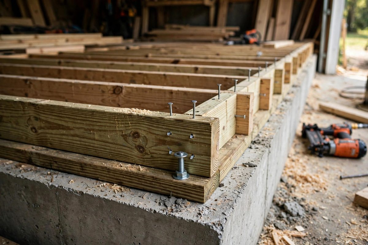
The rim joist caps the ends of the floor joists and ties the floor system together at the foundation, forming the perimeter that the walls sit on. Its fastening schedule, the size, type, and spacing of the fasteners connecting it to the sill plate and to each joist, is structural: get it wrong and the floor system can shift, the walls lose their anchorage, and the building fails to perform as designed. Here is how the schedule works and why each part matters.
What the rim joist does
The rim joist serves three structural roles: it closes the joist bays at the perimeter, it transfers lateral loads (wind and seismic) from the walls above into the floor diaphragm, and it provides nailing for wall sheathing and siding at the floor line. Because it sits at the load path's critical junction, its connections must handle both gravity and lateral forces. A rim joist that is merely toenailed in place may hold up the floor, but it cannot reliably transfer the lateral loads the building's engineering assumes.
Fastening rim to sill plate
The rim joist fastens down to the sill plate (which is anchored to the foundation) with nails or screws driven through the rim's bottom edge into the plate. Typical schedules call for 16d nails spaced about 6 inches on center along the rim, though local code governs and engineered plans may specify more. The connection must resist uplift and lateral sliding; in high-wind or seismic zones, metal connectors (hurricane ties or similar) supplement or replace nailing. Do not substitute shorter nails to save effort: the fastener must penetrate well into the sill plate to develop its rated strength.
Fastening rim to joist ends
Each joist end connects to the rim with end nails driven through the rim into the joist: typically three 16d nails per joist end in a staggered pattern, or the engineered equivalent in screws. This connection keeps the joists from rotating and ties them into the perimeter. Where the plans call for it, metal joist hangers or ties add capacity, particularly at beams and headers. Keep the nails out of the joist's very end grain center where splitting is likeliest; the staggered pattern exists to prevent the splits that weaken the connection.
Splices and corners
Rim joists splice where lengths run out, and splices need the same attention as the main runs: splice over a joist or solid blocking, never floating between joists, and nail the splice per the schedule on both sides. Corners get special treatment: the rim joists meet at the building's corners where lateral loads concentrate, so corner connections should be robust, with the schedule's full nailing plus blocking as needed. A weak corner undermines the whole perimeter's lateral capacity.
Code, inspection, and common errors
Follow the local building code and the engineered plans; the schedules in this article are typical practice, but the authority having jurisdiction sets the requirement, and it varies by wind zone, seismic zone, and occupancy. Common field errors include nailing too sparsely ("it looks fine"), using the wrong nail size, skipping the stagger pattern, and forgetting connectors in high-load zones. The framing inspector checks exactly these connections, because they are the ones that fail in storms. Build it to pass inspection the first time: the schedule is the minimum, not the aspiration.
Right fastener, right spacing, right pattern, at every joist, splice, and corner. The rim joist is a small member doing a large job; fasten it like it matters, because it does.
Related Guides
- Calculating Rim Joist Shear Capacities on Rim Sills: The rim joist is the quiet workhorse of floor framing. It caps the ends of the floor joists, ties them together, and transfers the edge loads of the
- Crown Orientation in Dimensional Floor Joists: Every dimensional lumber joist has a crown: a slight bow along its length, a legacy of how the tree grew and how the board dried. Installed
- Diagonal Wall Bracing for Tall Shed Framing: A tall shed, with walls eight feet or more and a roof catching wind like a sail, needs more than studs and sheathing to stand straight: it needs
- Staggering End Wall Stud Splices in High Wind Zones: End walls take the brunt of wind loads on a building, and in high wind zones every framing connection matters more. Stud splices, where two shorter
- Structural Top Plate Lap Spices on Load Bearing Walls: The top plate ties a framed wall together and carries the loads from above into the studs below. Where two plate sections meet, the splice must