
The tie beam is the unsung hero of the timber truss: while the rafters push outward under roof load, the tie beam pulls inward, holding the walls from spreading. Calculating its tension is the central structural question of the truss, because every joint, peg, and beam size downstream depends on that number.
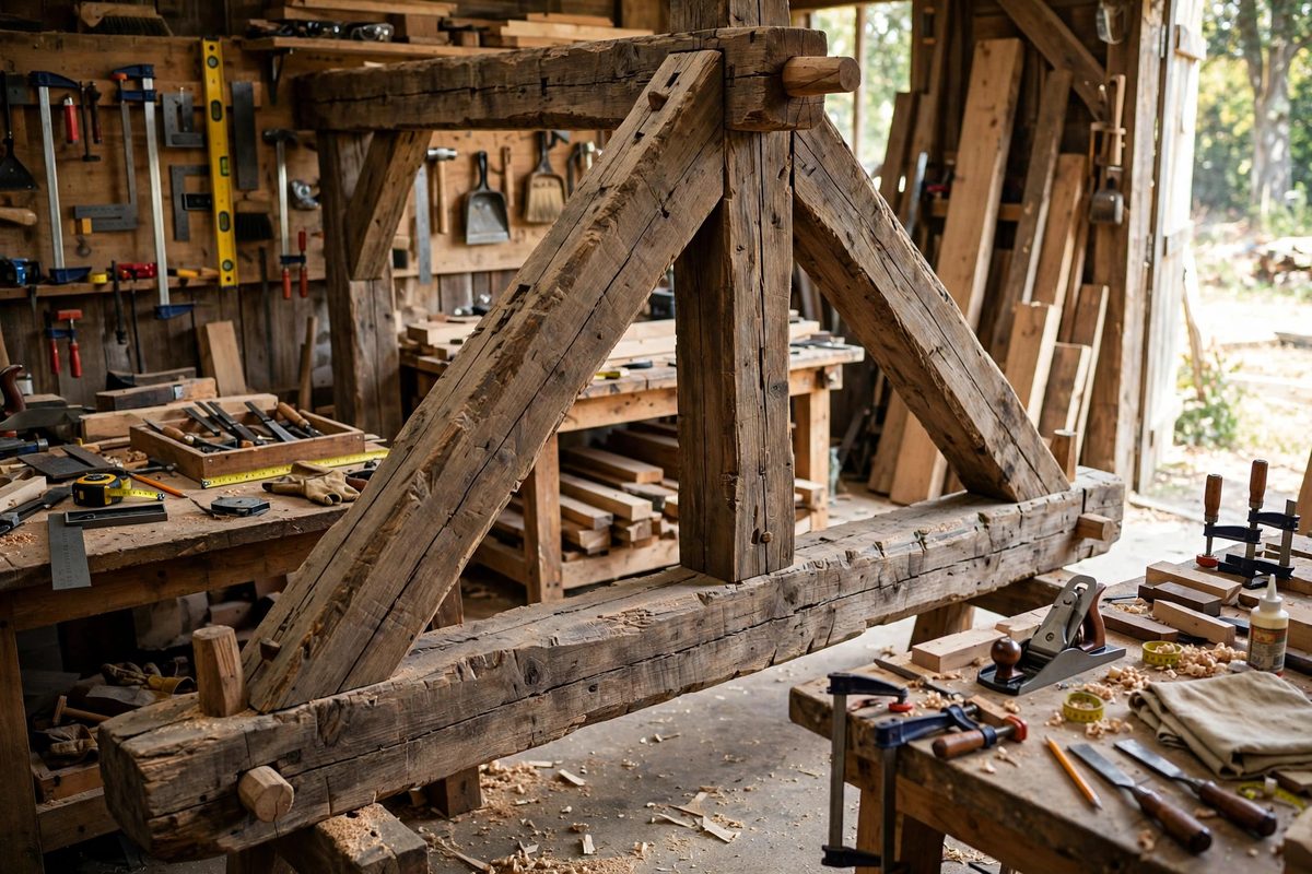
Where the Tension Comes From
A pitched roof turns vertical load into outward thrust at the eaves; the rafters act as inclined struts pushing down and out. Without a tie, the walls would spread and the roof would flatten. The tie beam spanning between the wall plates resists that thrust in pure tension. The tension magnitude depends on the roof load, the span, and the pitch: lower pitches generate more thrust for the same load, which is why shallow trusses need heavier ties. Snow, roofing material, and the truss's own weight all contribute to the load the tie must resist.
The Basic Calculation
For a simple king post or queen post truss under uniform load, the tie tension can be estimated from statics: resolve the rafter forces at the heel joint, and the horizontal component is the thrust the tie must resist. The thrust grows with the total load on the truss and with the span, and shrinks as the pitch steepens. Work through the joint equilibrium carefully, because the heel joint is where rafter compression, tie tension, and the wall reaction all meet. The calculation is straightforward trigonometry, but it must use the real loads: dead load of the roof build-up plus the design snow or live load for the location, not optimistic guesses.
Sizing the Beam for the Tension
Once the tension is known, size the tie beam so its net cross-section at the weakest point, usually at the joinery, carries the load with an appropriate safety factor. Timber in tension is strong along the grain, but joinery removes material: a mortise for the king post or a housing for the rafter heel reduces the effective section exactly where the tension is highest. Calculate the net area after joinery, not the gross beam size. Species matters too; the allowable tension stress varies between species and grades, so use the values for the actual timber going into the truss.
The Heel Joint Detail
The heel joint, where rafter meets tie at the wall plate, is the most stressed connection in the truss. It must transfer the rafter's thrust into the tie's tension without the rafter sliding off the end of the tie. Traditional solutions include the birdsmouth bearing combined with a wedged tenon, or a housed joint with pegs sized for the shear. The pegs or wedges carry real load here; undersized pegs shear and the joint walks. Detail the heel joint for the calculated thrust with the same care as the beam sizing, because a truss fails at its joints long before its members reach their limits.
Checking Deflection and Long-Term Behavior
Tension members stretch, and a tie beam under full load elongates slightly, letting the walls spread a small amount and the ridge settle. Keep the elongation small by sizing generously; a tie working near its limit also creeps over time under sustained load. Consider cambering the truss slightly during assembly so it settles into true under load rather than sagging below it. The truss should be checked after its first full loading season, since timber joints bed in and the initial settlement reveals whether the calculations held.
Calculate the thrust from real loads, size the tie for its net section at the joinery, detail the heel joint for the full force, and allow for settlement. The tie beam will then hold the roof's push quietly for generations, which is exactly what timber framing is for.
Related Guides
- Squaring Heavy Timber Posts With Plumb Bobs: A heavy timber post does not forgive being out of plumb. Once it is set and the joinery is cut, a lean you can barely see at the base becomes inches
- Scarf Joint Incline Angles for Structural Beam Splices: When a beam must be longer than the available lumber, the scarf joint splices two timbers end to end with long, overlapping angled cuts. The incline
- Point Load Transfer Through Bearing Partition Walls: Most walls in a house carry distributed loads: the weight of the floor or roof above spread along their length. But beams, girders, and headers
- Cantilever Deck Joist Overhang Limits and Ratios: A cantilevered deck joist extends past its supporting beam, creating the clean, post-free overhang that makes decks look like they float. It is an
- Cantilever Joist Deflection Ratios for Balconies: A balcony framed as a cantilever, joists extending past the building's support with no posts at the outer edge, is an elegant structure and an